
Calculating Applied Media Force During Vibratory Finishing
What appear to be identically set-up vibratory bowls will finish identical loads of parts in varying time cycles. This paper offers a new technique to better predict what the operator will produce, by measuring the force applied to the parts. It is the efficiency of that force which controls the efficiency and speed of the refinement cycle.
#surfin #research
Share
by William P. Nebiolo*
REM Chemicals, Inc.
Southington, Connecticut, USA
Editor’s Note: This paper is a peer-reviewed and edited version of a presentation delivered at NASF SUR/FIN 2016 in Las Vegas, Nevada on June 6, 2016. A printable PDF version is available by clicking HERE.
Featured Content


ABSTRACT
Despite conscientious attempts to equilibrate vibratory variables such as bowl amplitude, roll angle, media species, media volume, part loading, process liquid concentration and flow rate, what appear to be identically set-up vibratory bowls will nonetheless finish identical loads of parts in varying time cycles. Why is this so? This paper will explore this phenomenon. Techniques will be introduced that will allow operators to capture operational characteristics that aren't typically apparent. A formula will then be introduced that will allow operators to apply this new data to calculate the amount of force that the media is actually applying to the parts. It is the efficiency of the force applied to the parts during vibratory finishing that controls the efficiency and speed of the refinement cycle.
What is vibratory force?
During vibratory bowl processing, the bowl operating channel is converted into a fluidized bed of deburring media. Vibratory media is the tool that is used to either deburr or polish the parts placed into the machine.
The applied force this media can generate on the parts can be partially predicted using Newton's Second Law, F = ma, where the variable m equates to mass.1 In this paper m will be considered to be the weight of the media above the part at mid-channel.
The variable a equates to the acceleration of the mass.1 In other words, an accelerating media mass will apply a greater finishing force to the part surface as compared to a slower moving equivalent weight of media. The formula F = ma will be incorporated into a new formula that will be introduced later in this paper. When measurable process variables are inserted into the new formula, a better understanding of efficiency differences between apparently, identically operating vibratory bowls can be calculated.
How is mass m determined?
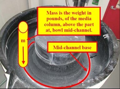
Figure 1 - Mass is the weight of the media column above a part at the bottom of the bowl at mid-channel.
Mass is the easiest variable to determine and in this paper, it is considered to be the weight, in pounds, of the media column, above the part at mid-channel, as shown in Fig. 1.
The poundage of mass is affected by:
- Available depth of the vibe bowl channel
- Attrition induced media depth reduction
- Weight density of the media being used
All types of vibratory media are affected by media attrition. With each passing hour a certain weight percentage of media is lost to frictional abrasion. It exits the bowl as swarf in the effluent flow stream.4,5,6 Therefore, microscopically, each individual piece of media decreases in volume every hour.5,6 Media attrition is most noticeable as a decrease in the height of media in the vibe bowl channel over time.
As the volume of media decreases, so too does the weight in pounds of media above the part at bowl mid-channel, as shown in Fig. 2.


Figure 2 - Image of a vibratory bowl (a) with the proper depth of media present in the bowl channel and (b) where the media depth is too low, caused by attrition.6
Figure 2(a) shows a properly loaded vibratory bowl channel.6 The channel has an available depth of 10 in. and it contains 10 in. of media at proper loading. This will allow optimal machine performance relative to media volume. Figure 2(b) shows the same vibe bowl after a prolonged period of running without adding media. The depth of media now measures just 6 in. With 4 in. of media lost to attrition, approximately 40% of the media volume is now missing. As a result, the weight in pounds of media in the column above the part is reduced comparably. If the reduced poundage of media in Fig. 2(b) is entered into the formula F = ma, then the amount of force F that the column of media above the part can apply is also reduced. Less applied force means more required time to accomplish the same amount of work.
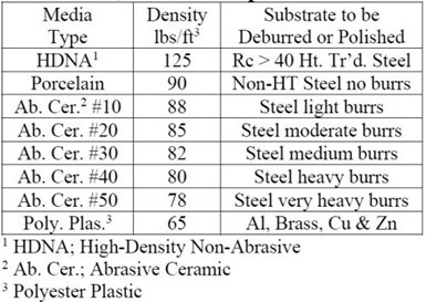
Table 1 - Media comparison table.
In vibratory finishing the species of media utilized is dependent upon the desired finish requirement for the parts and the speed with which the operation is to be performed (Table 1).5,6
A high-density, non-abrasive media is typically used for chemically accelerated finishing of hardened steel parts.5,6 Abrasive ceramic media is generally used for generic part deburring. Lighter-density, plastic media is used to minimize media impingement damage on metallurgically softer metals such as aluminum, brass, copper and zinc.
Vibratory bowls are sold by their volumetric displacement. Typically, larger volume machines have deeper channels and will hold more pounds of media. If we examine a small area at the bottom of the vibe bowl operating channel, a machine with a deep channel will hold a taller column of media mass above that same area. More media mass means more pounds of media and more mass m. The larger the mass the more force is applied to a part surface. As an example, consider a submarine (Fig. 3). The deeper the submarine dives, the more water pressure is applied to its hull, because there are more pounds of water above it.


Figure 3 - (a) A submarine near the surface has little water mass above its hull because the column of water above the submarine is virtually nonexistent; (b) a submarine at depth has significant water mass on its hull because the column of water above it is vast.
Mass rolling velocity
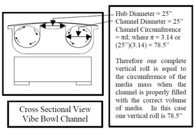
Figure 4 - This is a 45 ft3 vibratory bowl capable of holding 36 ft3 of media. It has a 25” wide channel. The vertical roll is 78.5” or the circumference of the 25” diameter circle formed by the media mass in the bowl channel, when properly filled with media.3,6
Mass rolling velocity can be measured as the distance a part travels per minute of time. The further the distance traveled per minute of time, the more work that is done in that minute of time because the part is contacted by the media more often.3 Mass movement in the vibratory bowl undergoes two, simultaneous planes of motion; vertical roll and horizontal slide.3,6 Vertical roll is shown in Fig. 4.
Vertical roll is the circumference of the circle formed where the width of the channel is the circle diameter.3,6 A vibratory bowl channel properly loaded with media will generate maximum circumference. When the media level is low due to attrition, the circle diameter is smaller, its resulting circumference is shorter and so too is the mass rolling distance. Horizontal slide is the distance required to lap the bowl channel one time (Fig. 5).
Calculation of mass velocity
Using the circumference information just described for vertical roll and horizontal slide, it is possible to calculate mass velocity as the distance parts travel per minute of processing time. Being able to complete this calculation is important to being able to later calculate the applied media force.
As an example, let us assume that a part placed in the 45 ft3 vibratory bowl makes four vertical rolls per one horizontal lap and that this action is completed in 60 seconds. This motion is shown in Fig. 7.
It is possible to calculate the part’s velocity or distance traveled per minute as follows:

Figure 5 - An overhead view of the 45 ft3 vibratory bowl shown in Fig. 4, illustrating the concept of horizontal slide.
Figure 5 shows an imaginary circle bisecting the vibe bowl operating channel. This circle is the average horizontal distance traveled because half the time parts are on the outside of this line and half the time they are on the inside. The horizontal distance traveled is calculated to be 157 in. Combining vertical roll and horizontal slide results in the helical, spiral, mass-motion pattern shown in Fig. 6.

Figure 6 - The mass helical motion pattern when vertical roll and horizontal slide are combined.6

Figure 7 - The helical motion pattern of four vertical rolls per horizontal lap in 60 seconds time.
Projecting Part Contact Area
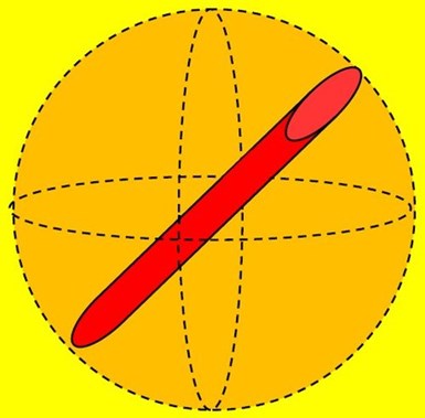
Figure 8 - Orthographic representation shows the sphere of volume within which the red cylinder rotates along its x, y and z axes.6
During vibratory processing, parts will move through and be contacted by the media mass orthographically.6 During an orthographic roll, a part, regardless of size and shape, will rotate about its x, y and z axes within a sphere of volume inscribed by its longest, or length, dimension (Fig. 8). At any one moment in time during vibratory processing, the orthographic rotational alignment of the part relative to its x, y or z axes is random and indiscriminate. We can assume however, that for the overall duration of the process cycle, its alignment to the media mass will be uniformly distributed relative to its x, y and z axes.
Since media force is applied to an area of the part, the question arises; “What one area of the part is being contacted at any one particular moment in time?” This is an unknown entity, as we can’t see the momentary alignment of the part within the media mass at any one moment and therefore the area contacted is an indeterminable variable.
It is possible however, to calculate a “part’s average area.” In orthographic rotation for the entire processing cycle, the average area is what will be forcefully contacted by the media at any moment in time.
Illustrative example: Average part area:
Let us assume that the red cylinder in Fig. 8 is a part 8 in. in length, 1 in. in width and 2 in. in height. Its average area can be determined by volumetric dimensions from the smallest box which envelops it, if it is placed flat on a table as follows:
Average part area calculation
1. Area length 1: (2 sides)(2 in.)(8 in.) = 32 in.2
2. Area length 2: (2 sides)(1 in.)(8 in.) = 16 in.2
3. Area of ends: (2 sides)(1 in.)(2 in.) = 4 in.2
4. Total Part O.D. area = 52 in.2
Therefore, the average contact area at any one time is:
5. 52 in.2 ÷ 6 sides = 8.67 in.2
Accordingly, we can say that on average, 8.67 in.2 of the part is being forcefully contacted by media at any one moment in time. This same model for calculating the average surface area of any shaped part can be used. Simply take the dimensions of the smallest rectangular box that will envelop the part.
Average surface area assumptions
Note that we must make two assumptions for the average area calculation above. They are:
- An ornately configured part will have an exact area that may be somewhat larger or smaller than the area of the box within which it can be contained. Even though this may be true, using the average area and not the exact area will be sufficient for comparing the efficiencies of identical machines in the vibratory processing room.
- The volume of the box enveloping the part has four-each, x-axis or length sides. By taking the average length area of the sum of the two narrow and two wide sides we can determine the average length area exposed to the media when the part is in the x-axis-orientation at the bowl’s mid-channel base.
Effect of centrifugal force
Centrifugal force via centrifugal barrel and centrifugal disc units reduce processing time,4 and this equipment is commonly found in finishing departments (Fig. 9).


Figure 9 - (a) A centrifugal barrel finisher; (b) a centrifugal disc finisher.
In a traditional vibratory bowl, a very slight centrifugal force is generated in the axial portion of the mass (Fig. 10).6
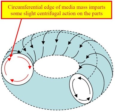
Figure 10 - Mass rolling action and location of the axial centrifugal force.6
The traditional formula for centrifugal force is given as F = mv2/r. By taking into consideration the force of gravity on the average surface area of the part by the column of media above it and combining the traditional mechanical engineering force formula of F = ma with the formula for centrifugal force we can generate a new formula that can be used to determine the force being applied to the average surface area of a part during vibratory processing. The new media contact force formula so created is shown as:
MCF = (m/g)(v2/r),
where formula variables are:
m = lb. of media column above the average area
g = gravity, a constant of 32 ft/sec2
v = part velocity in feet per second
r = radius of the media mass present
This formula is useful because it allows the vibratory operator to understand more fully how the following variables affect vibratory bowl performance:
1. Different media having different densities
2. Varying velocity; fast bowl vs. slow bowl
3. Different bowls with different channel radii
4. Attrition induced varying media radii
Determining the MCF variables
There are four variables which must be substituted into the MCF formula to determine media contact force. They are determined as follows:
m = Mass of media variable
To calculate the pounds of applied media mass above the part, we will use as an example:
1. The density of HDNA media found in Table 1.
2. The average part area of the part calculated previously (p. 5).
3. The 45 ft3 vibratory bowl containing, when properly loaded, 36 ft3 of media (Figs. 4 & 5).
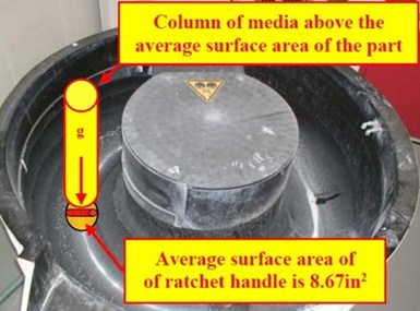
Figure 11 - The column of media above part average surface area.
The media applies a force equal to the weight in pounds of the column of media above the average surface area of the part. For this and all subsequent calculations using the MCF formula, it will be assumed that the part is centered at the base of the channel, congruent with the channel bisecting circle (Fig. 11).
Determine the weight in pounds of the media column above the average part surface area:
1. Weight of mass (lb.)
2. From Table 1: 1 ft3 HDNA = 125 lb./ft3
3. Average area of part = 8.67 in.2
4. Volume of column of media above average part area:
a. (8.67 in.2)(25 in.) = 216.75 in.3
b. 216.75 in.3 ÷ 1,728 in.3/ft3 = 0.125 ft3
5. Mass = (0.125 ft3)(125 lb./ft3) = 15.63 lb.
V = Velocity of part variable
The part velocity of 471 in./min., as discussed with Fig. 7. Converting to ft/sec:
1. 471 in/min ÷ [(12 in/ft)(60 sec/min)] = 0.654 ft/sec
Establishing a standard control model for the media contact force calculation
The standard control model for this example or any vibratory room, is the ideally set-up vibratory bowl. That is, the vibratory bowl that has the optimum velocity, media density and media level for the processing cycles being used. Substituting the variables just determined into the MCF formula, we will establish a standard control model for this paper. This model then becomes the standard against which other bowls are compared or the standard against which the bowl itself is compared in the future as operating conditions change. The MCF formula will be utilized to determine the pounds of media force applied to the average part surface area during finishing.
MCF variables for standard control
1. 45 ft3 bowl: channel diameter of 25 in. = 2.08 ft
2. Channel radius = 2.08 ft ÷ 2 = 1.04 ft
3. Gravity = 32 ft/sec2
3. Mass of applied media = 15.63 lb.
4. Mass velocity = 0.654 ft/sec
MCF calculations for standard control:
MCF = (m/g)(v2/r)
= [15.63 lb. ÷ 32ft/sec2][(0.654 ft/sec)2 ÷ 1.04ft]
= [0.488 lb./ft/sec2][0.428 ft2/sec2 ÷ 1.04ft]
= (0.488 lb./ft/sec2)(0.412 ft/sec2)
MCF = 0.201 lb. of media contact force
To understand how this is relevant to the performance of similar vibratory bowls in the same vibratory department, let’s now use the MCF to calculate the pounds of applied media force in three comparative examples that are relevant to normal vibratory room operating conditions.
MCF Example 1: The effect of media attrition
In this example, we assume that the standard control vibratory bowl has changed only in that the volume of media is 2 in. lower due to media attrition. Vibratory bowls having low media volumes are a typical inefficiency found in most vibratory departments. All other variables as determined for the standard control bowl situation will remain the same in this example.
The immediate effect of media attrition is that the column of media above the part average surface area is shorter. In this example, the column is 23 in. tall as compared to 25 in. tall for the standard control situation.
A secondary effect is that the circumference of the vertical rolling circle is shorter because the diameter of the media in the channel is now only 23 in. How does the loss of just two inches of media depth affect the applied media force on the part?
A media mass diameter of 23 in. means the circumference of the vertical roll has decreased from 78.5 in. to (π)(23 in.) = 72.22 in. If we assume the same four rolls per lap in 60 seconds noted earlier, the total distance traveled per minute or velocity is reduced from 471 in./min as follows:
1. Radius of media mass = 23 in. ÷ 2 = 11.5 in. = 0.96 ft.
2. Vertical distance (4)(72.22 in.) = 289 in.
3. Horizontal distance traveled = 157 in.
4. V = Distance per minute = 446 in./min = 37.17 ft/min = 0.62 ft/sec
The shorter column of media above the average surface area of the part decreases the weight in pounds of media above the part, calculated as follows:
1. Volume = (8.67 in.2)(23 in.) = 199.41 in.3 = 0.115 ft3 media
2. Weight = (0.115 ft3)(125 lb./ft3) = 14.38 lb.
Example No. 1 MCF calculation: 2 in. media loss by attrition
MCF = (m/g)(v2/r)
= [14.38 lb. ÷ 32 ft/sec2][(0.62 ft/sec)2 ÷ 0.96 ft]
= [0.449 lb./ft/sec2][0.38 ft2/sec2 ÷ 0.96 ft]
= (0.449 lb./ft/sec2)(0.40 ft/sec2)
MCF = 0.180 lb. of media contact force
MCF Example 2: The effect of the density of the media used
In this example, we will assume all variables are equivalent to the standard control vibratory bowl situation, except that, instead of filling the bowl with HDNA media from Table 1, the vibratory bowl has been filled with polyester plastic media at 65 lb./ft3. How will this change in media density affect the pounds of media contact force on the average surface area of the part?
The diameter of the media mass remains constant at 25 in. Therefore, the vertical roll distance remains the same at 78.5 in. However, the lighter density of the plastic media significantly changes the mass weight in pounds, in the media column above the average surface area of the part:
1. Volume = (8.67 in.2)(25 in.) = 216.75 in.3 = 0.125 ft3 media
2. Weight = (0.125 ft3)(65 lb./ft3) = 8.13 lb.
Example No. 2 MCF calculation: lighter density media
MCF = (m/g)(v2/r)
= [8.13 lb. ÷ 32 ft/sec2][(0.654 ft/sec)2 ÷ 1.04 ft]
= [0.254 lb./ft/sec2][0.428 ft2/sec2 ÷ 1.04 ft]
= (0.254 lb./ft/sec2)(0.412 ft/sec2)
MCF = 0.105 lb. of media contact force
MCF Example 3: The effect of a change in mass velocity
In this example, we return to the standard control operating conditions and make one variable change, assuming the four rolls per lap now requires 75 seconds instead of 60 seconds. This is a typical operational change in a vibratory department that can occur when a new processing run of parts is added to the bowl and the new load of parts weighs more than the original load of parts. In such instances the vibratory bowl is now moving more weight and as a result the rolling rate of the mass decreases. How will this change affect the media contact efficiency and therefore the process efficiency of the cycle?
The velocity calculation change is as follows:
1. Time = 60 sec ÷ 75 sec = 0.80
2. Velocity = (471 in./min)(0.80) = 377 in./min = 31.42 ft/min = 0.524 ft/sec
Example No. 3 MCF calculation: slower mass velocity
MCF = (m/g)(v2/r)
= [15.63 lb. ÷ 32 ft/sec2][(0.524 ft/sec)2 ÷ 1.04 ft]
= [0.488 lb./ft/sec2][0.275 ft2/sec2 ÷ 1.04 ft]
= (0.488 lb./ft/sec2)(0.264 ft/sec2)
MCF = 0.129 lb. of media contact force
MCF efficiency comparisons: standard control to the three examples
For comparison purposes, you will find the applied media force values for the standard control situation and the three examples just calculated in Table 2.

Table 2 - MCF efficiency differences.
Assuming that the standard control vibratory bowl scenario has been properly vetted and is the optimum operating condition for all similar-sized vibratory bowls in the vibratory room, performing an MCF calculation on each bowl will show how media contact force varies considerably from bowl-to-bowl. What were once often-ignored variables can now be utilized to understand performance inefficiencies and assist in increasing room performance.
Discussion of results
When setting up the vibratory department, it is critical to establish the most efficient and therefore optimum operational conditions. Obviously, this is necessary to ensure that the room is operating at peak efficiency and production throughput can be maximized for consumable cost efficiency.
Within each family of vibratory bowls, as determined by volumetric displacement, will be a set of operational characteristics related to velocity of the mass, depth of media in the channel and density of media used. When the standard control situation has been established, other bowls having the same volume can be compared to the standard control bowl using the MCF to determine why processing times vary from bowl-to-bowl.
Previously, vibratory bowl operational conditions were noted using an amplitude gauge. Although useful in capturing the most elemental basics of machine set-up, an amplitude gauge can’t be utilized to determine the performance differences between adjacent machines having varying processing cycle times. This is an aggravatingly maddening conundrum in situations where the operator is trying to match production cycles and part quality run-after-run in multiple side-by-side machines. By taking just a few measurements to determine mass velocity and the depth of missing media, MCF calculations can now be applied to adjacent machines of identical volumes to understand their performance differences.
As mentioned previously, loss of media volume due to attrition is the single most commonly found performance degradation characteristic in vibratory bowl finishing. The MCF in Example 1 showed how significant the loss of just 2 in. of media depth can be in machine performance. Such a loss is hardly noticed in most vibratory rooms, let alone is it addressed with the timely addition of new media to maintain media level. Yet the degradation of the machine performance would proceed unchecked, run-after-run, until significantly longer times were noticed. The use of the MCF can now be used to calculate answers to previous suppositions reflective of efficiency loss.
Likewise, in Example 2, the MCF calculation can be used to see how a change in media density will affect processing efficiency. There are situations that require the use of lighter or heavier density media. By using the MCF, it is now possible to predict the lengthening or shortening of the vibratory processing cycle as a consequence.
If we consider the bowl’s slower rolling speed, as in Example 3, the result of a heavier load of parts being placed into the bowl, in the past the only way to measure the bowl’s operation characteristics was by the use of an amplitude gauge. But by using MCF it is now possible to understand how the processing time will be lengthened, the result of the slower speed.
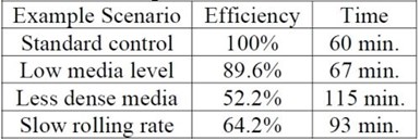
Table 3 - Projected cycle time differences resulting from the three previous examples correlated to 1 hour.
Table 3 allows us to view the projected changes in processing time as a result of the three comparison examples.
Conclusions
Vibratory finishing efficiency is dependent upon several variables that are most definitely synergistically interrelated. This paper has identified the most critical variables, has described procedures to measure them and has introduced a formula into which the quantitatively measured variables can be substituted to generate qualitatively important performance information.
This paper has additionally shown how the change of one variable such as media depth is synergistically related to distance travelled and then mass velocity. Previously, operators may have supposed an interrelationship between the two but were impotent in capturing and quantifying their suppositions. The introduction of the MCF has given them that tool.
Optimizing performance in the vibratory room is critical for time and consumable efficiency. Attention to operational details is important in maintaining this efficiency. It is now possible to not only understand that these variables exist but to also use them to generate a performance advantage or correct inadequacies where and when possible.
References
1. J. Lucas, Live Science Website, Force, Mass & Acceleration: Newton's Second Law of Motion, June, 2014; www.livescience.com/46560-newton-second-law.html .
2. Naval-Technology.com; Image of U.K. Astute Class, SSN Nuclear Submarine; 2002
3. W.P. Nebiolo, "An Easily Understood Technique for Measuring Vibratory Bowl Speed and Optimizing Vibratory Bowl Processing Efficiency," Proc. SUR/FIN '07, Cleveland, OH, 2007.
4. W.P. Nebiolo, "A Comparison of the Advantages and Disadvantage of Assorted Mass Finishing Techniques," Proc. SUR/FIN '09, Louisville, KY, 2009.
5. W.P. Nebiolo, "Estimating the Total Solids Burden during the Waste Water Treatment of Vibratory Finishing Effluents," Proc. SUR/FIN '11; Rosemont, IL, 2011.
6. W.P. Nebiolo, REM Training Manual Edition No. 9; REM Chemical, Inc.; Southington, CT; Dec. 30, 2014.
7. www.subsim.com; website; radio room forum; silent hunter, periscope and antennas fix images.
Footnotes
*Corresponding author:
William P. Nebiolo
REM Surface Engineering
325 West Queen Street
Southington, CT 06489
Phone: (860) 621-6755
Cell: (860) 985-3758
E-mail: wnebiolo@aol.com
About the author

He joined the NASF as a member of the Waterbury Branch of AES in 1978. Working his way through the branch officers’ chairs, Bill served as Waterbury Branch President 1984-85 and was appointed Branch Secretary in 1991. Bill spearheaded the merger of the Waterbury, Bridgeport and Hartford Branches into the Connecticut Branch in 2004, then petitioned and was awarded branch certification through AESF National. Bill was immediately appointed Connecticut Branch Secretary and remains in the role to this day. He has represented the Connecticut Branch as a NASF National Delegate, has served as a technical chair at several NASF SUR/FIN technical sessions was awarded an NASF National Award of Merit in 2010 and in 2012 was elevated to the position of Connecticut Branch Honorary member.
To date, Bill has published a dozen papers in assorted technical journals and presented more than 20 papers at technical conferences and seminars. From 1996-2000 Bill served as one of SME’s Mass Finishing Technical Training Program instructors at more than two dozen training sessions. Bill is the author of the SME Mass Finishing Training Book and the REM Training Manual, which is now in its 9th edition.
RELATED CONTENT
-
Black Chromium Finishing: Beauty and the Beast
Over the past 10 years, there has been commercial development of black chromium deposits from a trivalent chromium electrolyte. This paper will review the deposit characteristics and operational consideration of these similar, but different chromium plating deposits.
-
A Pulse/Pulse Reverse Electrolytic Approach to Electropolishing and Through-Mask Electroetching
Research at the authors’ laboratories has focused on pulse/pulse reverse electrolysis on cathodic processes, such as hard chromium plating from non-hexavalent chemistries. This papers describes studies into pulse/pulse reverse electrolysis as applied to electrochemical metal removal processes, such as electropolishing and electroetching.
-
A Process for Alkaline Non-cyanide Silver Plating for Direct Plating on Copper, Copper Alloys and Nickel Without a Silver Strike Bath
Traditionally, silver is electroplated in toxic, cyanide-based chemistry. Due to cyanide’s extreme hazard to human health and environments, developing non-cyanide silver chemistry is essential for the silver electroplating industry. Discussed here is an aqueous, alkaline non-cyanide silver plating technology, which can be directly plated over nickel as well as copper and its alloys. The silver deposits have perfect white color and better anti-tarnishing properties than other non-cyanide silver processes. The silver is plated entirely from the dissolving silver anode and the bath is very stable, and maintains a stable pH level both during plating and idle time. This new non-cyanide silver technology will plate bright silver that is perfectly suitable for electronic, industrial and decorative applications. .


