Laser-Induced Selective Deposition on Metal Using Electroless Gold
Originally published as H.R. Khan, M.U. Kittel and Ch. J. Raub, Plating and Surface Finishing, 75 (8), 58-64 (1988), this paper was awarded the 1989 AESF Gold Medal. The idea was to see if shining a laser on the substrate during electroless gold plating had any significant effect. The results are presented here.
#research
Featured Content
by
H.R. Khan, M.U. Kittel and Ch. J. Raub
Editor’s Note: Originally published as H.R. Khan, M.U. Kittel and Ch. J. Raub, Plating and Surface Finishing, 75 (8), 58-64 (1988), this paper was awarded the 1989 AESF Gold Medal for Best Paper published in Plating and Surface Finishing in 1988. A printable version of this paper is available by clicking HERE.
ABSTRACT
Gold is selectively deposited on thin layers of nickel and silver on epoxy resin plates using electroless gold baths of various stabilities and a focused beam from an argon-ion laser. The effects of laser-beam intensity, substrate material, layer thickness and electrolyte stability on deposition and electrode potential were investigated. Deposit morphology was studied by scanning electron microscopy and compared with the morphology of deposits from electroless baths heated to 80°C without laser irradiation.
Introduction
Laser-induced selective metal deposition on metallic and non-metallic substrates has been the subject of much attention recently. An induced deposition rate several orders of magnitude greater than conventional rates is claimed to occur at points where a laser beam impinges the electrode surface. Laser-enhanced deposition of nickel, copper, gold and palladium from electroless baths has been reported,1-6 with the increased plating rate at the point of the laser beam attributed to heating of the electrolyte/electrode interface, increased convection and electrochemical changes.
This technique seems promising for precious metal contact and microelectronic applications because it works well on small, localized areas, does not require masking, and provides high deposition rates. The results of a study on laser-induced electroless gold deposition on thin layers of silver and nickel on an epoxy resin substrate are reported in this paper.
Experimental procedure
An argon-ion laser of variable power (1 to 5 watts) was focused on the substrate in an electrolyte. The power density at the electrode was several kW/cm2. The substrate was close to the beam, generating a gold deposit of about 100 to 160 μm in diameter. Details of the laser system are described elsewhere.7
Table 1 - Electroless baths used for laser-enhanced deposition.
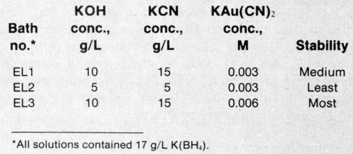

Figure 1 - Typical potential-vs.-time curve for an electroless gold bath with and without stabilizer.
Three electroless gold solutions (Table 1) with varying amounts of KOH, KCN, K[Au(CN)2] and K(BH4) were used. The chemical composition of the baths is one stability-determining factor. Stability was measured using a method developed by the authors.8-10 The mixed potential vs. time was measured after a decomposition-causing solution was added to the operational electrolyte. In this type of electrolyte, the mixed potential/time curve jumps quickly to more negative values once precipitation of the metals begins. Depending on the type of electrolyte, addition agents and bath condition, decomposition will be delayed when compared to a freshly prepared reference electrolyte with or without additives. Typical curves and the effect of a stabilizer are shown in Fig. 1. As a measure of stability (S), time twith:time twithout a stabilizer is a convenient ratio. Stable baths have high S values, whereas unstable baths exhibit low values.
The surface of 1-mm-thick plates of epoxy resin (1×2 cm) was activated by a Pd-Sn solution before being electroplated with 2-, 10-, or 20-μm-thick layers of silver or nickel prior to gold deposition. Samples were exposed to a laser beam for a period of 2 min in the electrolyte. Changes in the electrode (substrate) potential were recorded against a standard calomel electrode (SCE) and later corrected against a normal hydrogen electrode (NHE). Deposit morphology was investigated using a scanning electron microscope.
Gold over nickel
The variation of electrode potentials as a function of time during the laser-induced deposition of gold on 10-μm-thick nickel is shown in Fig. 2. Three electrolytes (baths) at five laser power levels (1 to 5 W) were used. The electrode potential increased as bath stability increased and decreased as laser power increased. Figure 3 shows the laser-induced gold deposits from three baths; the edge sharpness of the deposits increased with increased bath stability as long as the thickness of the substrate remained constant.
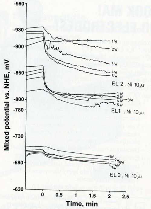
Figure 2 - Mixed potential as a function of time for laser-induced gold deposition from Baths EL1, EL2 and EL3 (the most stable) on 10-μm-thick nickel.
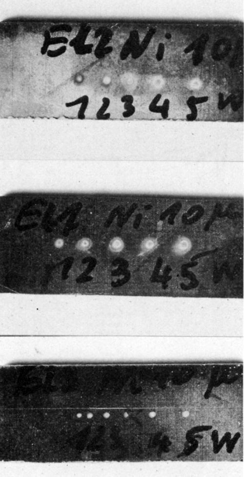
Figure 3 - Photos of laser-induced (at 1 to 5 W) gold deposits from (a) Bath EL2, (b) Bath EL1, and (c) Bath EL3 on 10-μm-thick nickel on epoxy. Magnification was 29×, 25× and 33× for Deposits a-c, respectively.
The edges of the gold deposits from the most stable bath (EL3) were very sharp (Fig. 3c); gold was deposited only on the area directly exposed to the laser beam.
Figure 4 shows the morphology of the gold deposits at 5 W of laser power. Smaller grains are distributed among the larger grains; the small grains become even finer as bath stability increases.
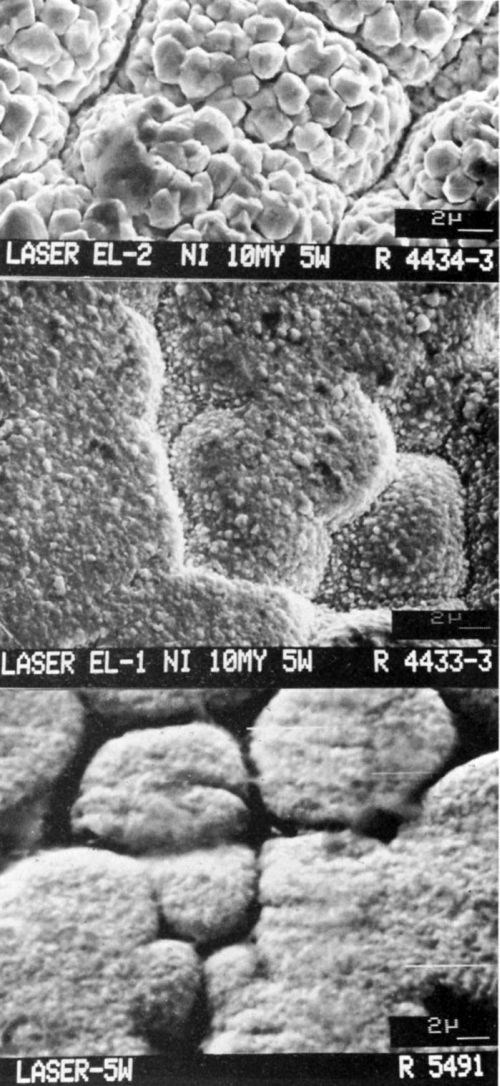
Figure 4 - SEMs (3500×) of laser-induced (at 5 W) gold deposits from (a) Bath EL2, (b) Bath EL1 and (c) Bath EL3 on 10-μm-thick nickel on epoxy.
To study the effect of nickel thickness on gold deposition, the most stable electrolyte, EL3, was chosen for gold plating on 2-, 10-, and 20-μm-thick nickel. The gold spots on 2- and 20-μm-thick nickel (Figs. 5a and 5c, respectively) were larger than the laser-beam points; this fact was attributed to lateral spreading of the heat generated by the laser beam. For the 10-μm-thick nickel, gold deposition was selective and limited to irradiated areas (Fig. 5b). The electrode potentials for 10-μm-thick nickel were less negative than those for 2- or 20-μm-thick nickel (Fig. 5).
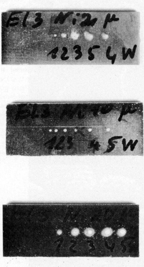
Figure 5 - Photos (34×) of laser-induced (at 1 to 5 W) gold deposits from the three baths on (a) 2 μm of Ni, (b) 10 μm of Ni, and (c) 20 μm of nickel.
Bath EL3 was also used to study mixed electrode potential as a function of time. Figure 6 shows that the mixed potential in the most stable bath is less negative over 10 μm of nickel than over 2 or 20 μm.
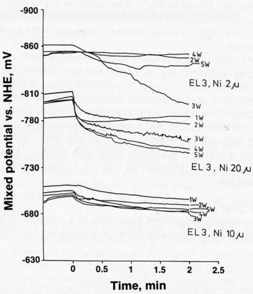
Figure 6 - Mixed potential as a function of time for laser-induced gold deposition from Bath EL3 on 2-, 10-, and 20-μm-thick nickel.
Gold over Silver
Figure 7 presents electrode-potential data for gold over silver. The curves are similar to those for gold over nickel. The electrode potential in the most stable electrolyte (EL3) is less negative than the potentials in the other solutions.
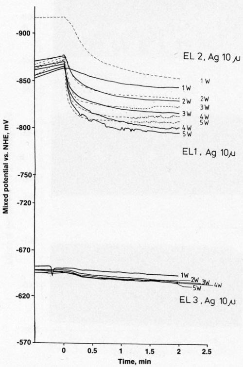
Figure 7 - Mixed potential as a function of time during laser-induced gold deposition on 10-μm-thick silver.
All the laser-induced gold deposits on 10-μm-thick silver layers from three different electrolytes had a thin layer of gold outside the directly laser-irradiated gold spots (Figs. 8a-c). The deposition rate on silver was much higher than that on nickel, and the gold spots were about three times larger on silver than on nickel. This spreading of spots can be explained by the greater thermal conductivity of the silver. Bath EL3, which produced the sharpest gold deposits on nickel, produced no gold deposit on silver. Figure 9 shows that gold deposited on silver from Bath EL1 had finer grains than those from Bath EL2.
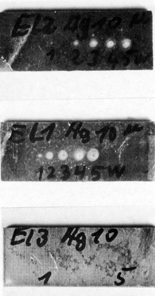
Figure 8 - Photos of laser-induced (at 1 to 5 W) gold deposits from (a) Bath EL2, (b) Bath EL1, and (c) Bath EL3 on 10-μm-thick silver. Magnification was 27×, 20×, and 31× for Deposits a-c, respectively.
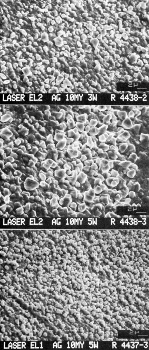
Figure 9 - SEMs of gold deposited on 10-μm-thick silver on epoxy using (a) Bath EL2 and 3 W of laser power, (b) Bath EL2 and 5 W, and (c) Bath EL1 and 5 W.
Effect of laser power
The electrode potential became less negative as the laser power was increased from 1 to 5 watts (Fig. 2); the size of the gold spot also increased as the power increased. However, the difference between the starting and final electrode potentials (Es - Ef) became smaller with increasing bath stability.
Tables 2-4 list starting potentials at time = 0 (laser turned off), final potentials after 2 min of irradiation, the difference between potentials at time = 0 and time = 2, and the difference between potentials after irradiation at various wattages. A comparison of the data in Tables 2-4 with SEMs of the gold deposits reveals that there is no direct relationship between the laser wattage used and the structure of the deposits.
Table 2 - Electrode potentials for 10 μm-thick nickel layers.a
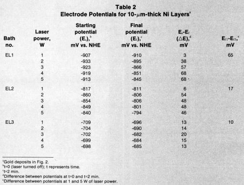
Table 3 - Electrode potentials in Bath EL3 for nickel layers.a
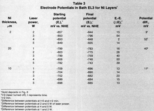
Table 4 - Electrode potentials for 10 μm-thick silver layers.a
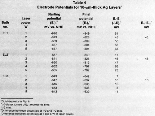
However, the small potential difference from 1 to 5 W for Bath EL3 (Fig. 2, bottom), corresponds to sharp-edged gold spots (Fig. 3c) with a fine-grained structure (Fig. 4c). Large potential differences, such as those that occurred with Bath EL2 (Fig. 2, top) seem to result in dark, smeared-out spots (Fig. 3a) with fairly coarse grains (Fig. 4a).
The change in potential after turning on the laser (i.e., the gradient of the electrolyte potential between ambient and laser temperature) does not seem to be critical. More important is the gradient in the higher temperature range (80 to 150°C) generated by 5 W of laser power.12 This gradient is a measure of the activity of the gold-deposition process in the electroless bath. Furthermore, the formation of "thermal batteries" during laser heating of the cathode and the change in the active surface (from nickel or silver to gold) must be considered. Application of a small potential before irradiation had little effect on deposits under the conditions investigated.
The microstructure of the gold deposits on 10-μm-thick nickel layers is shown in Figs. 10a-d. The grain size of the deposits decreased with lower laser wattages because the rate of deposition was slow compared to the rate obtained with higher wattages.

Figure 10 - SEMs (3500×) of gold deposited on 10-μm-thick nickel on epoxy using (a) Bath EL2 and 5 W of laser power, (b) Bath EL2 and 3 W, (c) Bath EL2 and 1 W, and (d) Bath EL1 and 1 W.
Figure 11 shows the structure of electroless gold from Bath EL1, which contained 15 g/L KCN and was heated to 80°C by conventional methods rather than by a laser beam. The deposit has a fine, needle-like structure, whereas the laser-induced deposit from the same electrolyte contained small cubic particles (Fig. 9c). When the concentration of KCN in the 80°C electroless bath was reduced to 10 g/L , the deposit structure (Fig. 12) resembled that in Fig. 9c.
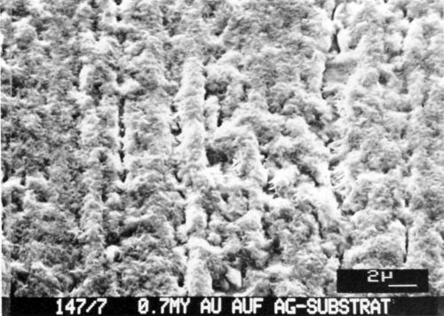
Figure 11 - SEM of gold deposited from Bath EL1 (15 g/L KCN, 80°C) on silver.
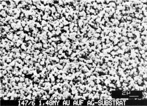
Figure 12 - SEM of gold deposited from Bath EL1 (10 g/L KCN, 80°C) on silver.
From this study, the authors concluded that in electroless gold baths, the chemistry of the bath and the heating of the cathode and/or the cathodic layer have a dominant effect on deposition.
Discussion
Deposition mechanisms of electroless gold electrolytes have been discussed extensively in the literature,11 but a complete understanding of the process still eludes researchers. The electrolyte certainly is kept in a metastable condition by addition agents in order to prevent decomposition.
Temperatures in excess of established operating temperatures will enhance the decomposition rate, or nuclei formation and growth, especially if catalysis at activated sites on the substrate is no longer inhibited. Laser irradiation thus provides energy for the reduction reaction, increases the diffusion rate of ions to growth sites, and accelerates surface diffusion. These are processes that promote grain growth; a coarse structure is formed at higher laser wattages on low-heat-conducting substrates. Unexplainable complications occur when stabilizer molecules are adsorbed on nucleation sites or growth planes; in general, adsorption decreases at high temperatures.
However, no definite predictions can be made for these gold electrolytes with Au-Co solutions.12 There was no continuous increase in grain size with temperature. The largest grains were observed at 90°C; grains were smaller when either higher or lower process temperatures were used. The adsorption maxima of either additives (stabilizers) or the decomposition products of electrolyte constituents certainly may play a role in the complicated interplay between nuclei formation and growth. In general, nuclei growth is promoted by higher temperatures and reduced by the use of appropriate additives.
An interesting topic for future work might be a study of the role of AuCN in electroless gold baths.
Acknowledgments
The authors wish to thank the Arbeitsgemeinschaft Industrieller Forschungsvereinigungen (AIF), Cologne, W. Germany, for supporting this study from funds of the Bundesministerium für Wirtschaft (BMW).
References
1. R.J. von Gutfeld, et al., App. Phys. Lett., 35, 651 (1979).
2. R.J. von Gutfeld and J.Cl. Puippe, Oberflächen-Surface, 11, 294 (1981).
3. J.Cl. Puippe, R.E. Acosta and R.J. von Gutfeld, J. Electrochem. Soc., 128, 2539 (1981).
4. R.J. von Gutfeld, M. Gelchenski and L.T. Romankiw, ibid., 128, 448c (1981).
5. F. Friedrich and Ch.J. Raub, Metalloberfläche, 38, 237 (1984).
6. F. Friedrich and Ch.J. Raub, Galvanotechnik, 77, 2658 (1986).
7. H.R. Khan and Ch.J. Raub, to be published.
8. M.U. Kittel and Ch.J. Raub, Metalloberfläche, 41 (7), 309 (1987).
9. M.U. Kittel and Ch.J. Raub, ibid., 42 (2), 75 (1988).
10. M.U. Kittel, Ch.J. Raub and E. Weiss, ibid., 42, 7 (1988).
11. Y. Okinaka, Plating, 57, 914 (1970).
12. H.R. Khan, M. Baumgartner and Ch.J. Raub, Proc. Symp. on Electrodeposition Technology, Theory and Practice, Vol. 87-17, The Electrochemical Soc, 1987; p. 165.
About the authors

Hamid R. Khan is a staff scientist at the Forschungsinstitut für Edelmetallie und Metallchemie (FEM), Katherinenstr. 17, 7070 Schwabisch Gmund, W. Germany 07171-62054. He is also an adjunct professor in the Dept. of Physics and Astronomy, University of Tennessee, Knoxville, TN. Dr. Khan holds a Ph.D. degree from Louisiana State University. His research interests include synthesis and property evaluation of materials such as thin films.
Martin U. Kittel is employed at the FEM, where his work centers on electroplating. He holds a diploma from the Fachhochschule Technical College, Aalen.
Dr. Christoph Julius Raub has been head of the FEM since 1970. Before that, he was a research physicist at the University of California at San Diego, and head of the W.C. Hereaus Metals Research Laboratory, Hanau. He studied chemistry and physics at the University of Munster.
RELATED CONTENT
-
Masking for Surface Finishing
Masking is employed in most any metal finishing operation where only a specifically defined area of the surface of a part must be exposed to a process. Conversely, masking may be employed on a surface where treatment is either not required or must be avoided. This article covers the many aspects of masking for metal finishing, including applications, methods and the various types of masking employed.
-
Stripping of Plated Finishes
The processes, chemicals and equipment, plus control and troubleshooting.
-
An Overview of Electroless Nickel Plating
By definition, electroless plating is metal deposition by a controlled chemical reaction.


